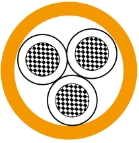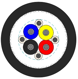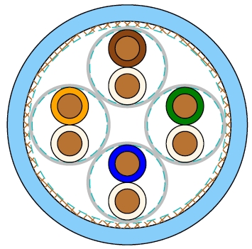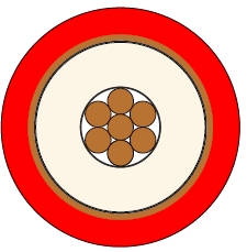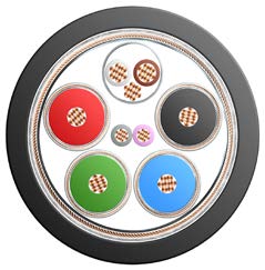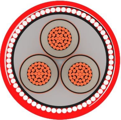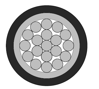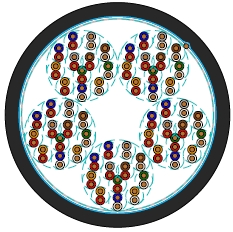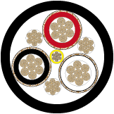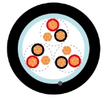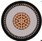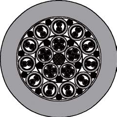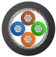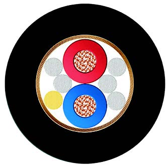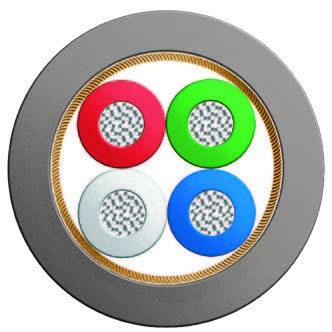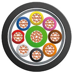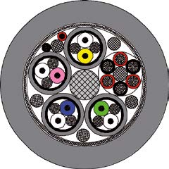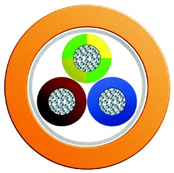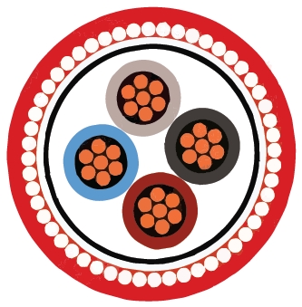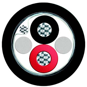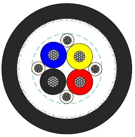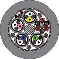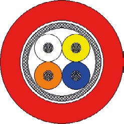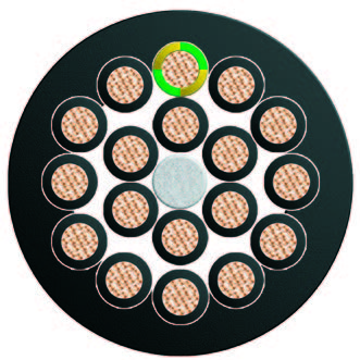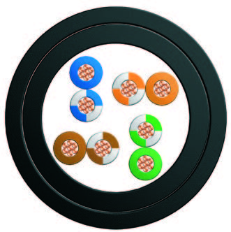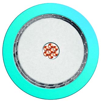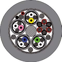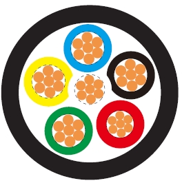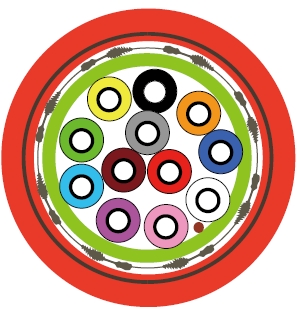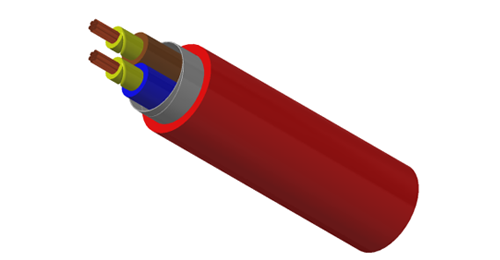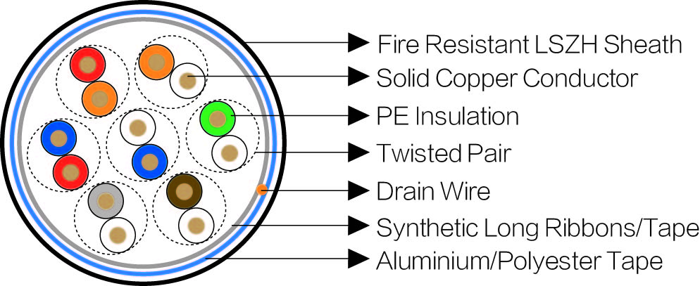
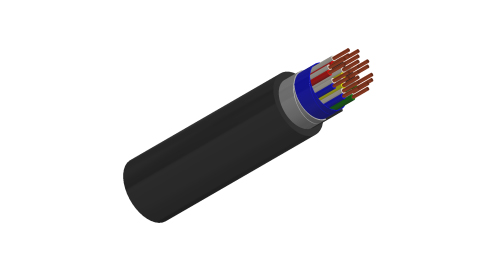
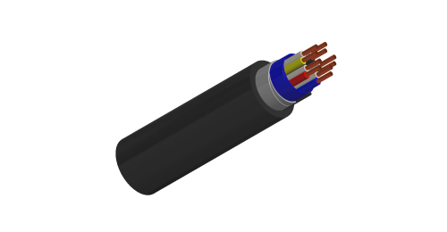
K24 serves remote-control and teletransmission circuits in underground and suburban railway networks. Solid copper conductors with PE insulation form twisted pairs. An aluminium/polyester tape screen, tinned copper drain wire and flame-retardant LSZH sheath complete the unarmoured construction. The armoured option adds bedding, double steel tapes and an LSZH outer sheath. Choose the version to suit the route’s mechanical protection and installation-space requirements.
AFNOR NF F 55-624
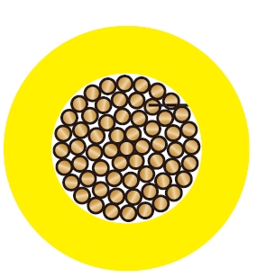
Electrical Characteristics at 20℃Conductors: Solid copper conductor, 0.5/0.6/0.9 mm nominal diameter.
Insulation: Polyethylene insulation.
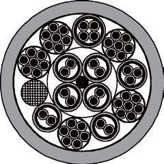
Cabling Element: Each two conductors are twisted together to form a pair.
Stranding: For cables less than 15 pairs, pairs are helically stranded in concentric layers to form the cable core. For cables from 21 to 112 pairs, pairs are stranded in concentric layers or bundles to form the cables core.
Core Wrapping: One or more synthetic long ribbons or tapes are arranged on the cable core.
Screen: Aluminium/Polyester tape.
Drain Wire: A tinned copper drain wire, 0.5mm nominal diameter.
Sheath: Fire retardant LSZH.
Optional:Armoured Cables: For armoured cable, one or more tape(s) is (are) helically applied with overlap on the screen to form a bedding, and double steel tapes armour with a halogen-free fi re retardant outer sheath are applied on the bedding.
| Nominal Conductor Diameter | mm | 0.5 | 0.6 | 0.9 |
| Minimum Insulation Resistance | MΩ.km | 5000 | 5000 | 5000 |
| Maximum Operating Voltage | V | 200 | 200 | 400 |
| Maximum Permissible Current | A | 0.25 | 0.35 | 0.80 |
Minimum Bending Radius: 7.5×OD (unarmoured); 10×OD (armoured)
Temperature Range: -40℃ to +60℃ (during operation); -20℃ to +50℃ (during installation)
| Cable Code | Number of Pairs (n) | Nominal Sheath Thickness mm | Nominal Overall Diameter mm | Nominal Weight kg/km |
|---|---|---|---|---|
| 0.5mm Conductor, 0.9mm Insulated Wire | ||||
| BRAIL K24-2Y(L)H-2P0.5 | 2 | 1.0 | 6.0 | 55 |
| BRAIL K24-2Y(L)H-3P0.5 | 3 | 1.0 | 6.5 | 65 |
| BRAIL K24-2Y(L)H-5P0.5 | 5 | 1.0 | 7.0 | 80 |
| BRAIL K24-2Y(L)H-7P0.5 | 7 | 1.0 | 8.0 | 95 |
| BRAIL K24-2Y(L)H-10P0.5 | 10 | 1.0 | 9.0 | 120 |
| BRAIL K24-2Y(L)H-15P0.5 | 15 | 1.2 | 10.5 | 150 |
| BRAIL K24-2Y(L)H-21P0.5 | 21 | 1.2 | 12.5 | 185 |
| 0.6mm Conductor, 0.96mm Insulated Wire | ||||
| BRAIL K24-2Y(L)H-2P0.6 | 2 | 1.0 | 6.5 | 65 |
| BRAIL K24-2Y(L)H-3P0.6 | 3 | 1.0 | 7.0 | 70 |
| BRAIL K24-2Y(L)H-5P0.6 | 5 | 1.0 | 8.0 | 90 |
| BRAIL K24-2Y(L)H-7P0.6 | 7 | 1.0 | 8.5 | 110 |
| BRAIL K24-2Y(L)H-10P0.6 | 10 | 1.2 | 10.0 | 140 |
| BRAIL K24-2Y(L)H-15P0.6 | 15 | 1.2 | 11.5 | 175 |
| BRAIL K24-2Y(L)H-21P0.6 | 21 | 1.2 | 13.5 | 225 |
| 0.9mm Conductor, 1.5mm Insulated Wire | ||||
| BRAIL K24-2Y(L)H-2P0.9 | 2 | 1.0 | 8.5 | 95 |
| BRAIL K24-2Y(L)H-3P0.9 | 3 | 1.0 | 9.0 | 110 |
| BRAIL K24-2Y(L)H-5P0.9 | 5 | 1.0 | 10.5 | 150 |
| BRAIL K24-2Y(L)H-7P0.9 | 7 | 1.2 | 12.0 | 185 |
| BRAIL K24-2Y(L)H-10P0.9 | 10 | 1.2 | 13.5 | 245 |
| BRAIL K24-2Y(L)H-15P0.9 | 15 | 1.4 | 15.0 | 340 |
| BRAIL K24-2Y(L)H-21P0.9 | 21 | 1.4 | 19.0 | 435 |
| Cable Code | Number of Pairs (n) | Nominal Sheath Thickness mm | Nominal Overall Diameter mm | Nominal Weight kg/km | |
|---|---|---|---|---|---|
| Inner | Outer | ||||
| BRAIL K24-2Y(L)HBH-2P0.5 | 2 | 1.0 | 1.0 | 10.0 | 195 |
| BRAIL K24-2Y(L)HBH-3P0.5 | 3 | 1.0 | 1.0 | 10.5 | 205 |
| BRAIL K24-2Y(L)HBH-5P0.5 | 5 | 1.0 | 1.0 | 11.0 | 230 |
| BRAIL K24-2Y(L)HBH-7P0.5 | 7 | 1.0 | 1.0 | 12.0 | 255 |
| BRAIL K24-2Y(L)HBH-10P0.5 | 10 | 1.0 | 1.0 | 13.0 | 295 |
| BRAIL K24-2Y(L)HBH-15P0.5 | 15 | 1.0 | 1.2 | 14.5 | 345 |
| BRAIL K24-2Y(L)HBH-21P0.5 | 21 | 1.0 | 1.2 | 16.5 | 400 |
| 0.6mm Conductor, 0.96mm Insulated Wire | |||||
| BRAIL K24-2Y(L)HBH-2P0.6 | 2 | 1.0 | 1.0 | 10.5 | 200 |
| BRAIL K24-2Y(L)HBH-3P0.6 | 3 | 1.0 | 1.0 | 11.0 | 210 |
| BRAIL K24-2Y(L)HBH-5P0.6 | 5 | 1.0 | 1.0 | 12.0 | 245 |
| BRAIL K24-2Y(L)HBH-7P0.6 | 7 | 1.0 | 1.0 | 12.5 | 285 |
| BRAIL K24-2Y(L)HBH-10P0.6 | 10 | 1.0 | 1.2 | 14.0 | 330 |
| BRAIL K24-2Y(L)HBH-15P0.6 | 15 | 1.0 | 1.2 | 15.5 | 385 |
| BRAIL K24-2Y(L)HBH-21P0.6 | 21 | 1.0 | 1.2 | 18.0 | 450 |
| 0.9mm Conductor, 1.5mm Insulated Wire | |||||
| BRAIL K24-2Y(L)HBH-2P0.9 | 2 | 1.0 | 1.0 | 12.5 | 260 |
| BRAIL K24-2Y(L)HBH-3P0.9 | 3 | 1.0 | 1.0 | 13.5 | 285 |
| BRAIL K24-2Y(L)HBH-5P0.9 | 5 | 1.0 | 1.0 | 14.5 | 345 |
| BRAIL K24-2Y(L)HBH-7P0.9 | 7 | 1.0 | 1.2 | 16.0 | 395 |
| BRAIL K24-2Y(L)HBH-10P0.9 | 10 | 1.0 | 1.2 | 18.0 | 485 |
| BRAIL K24-2Y(L)HBH-15P0.9 | 15 | 1.0 | 1.4 | 19.5 | 610 |
| BRAIL K24-2Y(L)HBH-21P0.9 | 21 | 1.0 | 1.4 | 24.0 | 735 |
0.5, 0.6 and 0.9 mm nominal conductor diameters in the listed constructions.
Screened twisted pairs with a 0.5 mm nominal tinned copper drain wire.
Separate armoured and unarmoured tables, each with size-specific dimensions.
Identify conductor diameter, pair count and armour requirement in the cable schedule. Use the matching construction’s overall diameter and minimum bend radius: 7.5 times diameter for unarmoured cable or 10 times for armoured cable. Select the circuit voltage from the appropriate conductor-size column and specify the required fire-performance documents for the route.
Which conductor diameters are listed?
This K24 range lists 0.5, 0.6 and 0.9 mm solid copper conductors. These values are diameters, not cross-sectional areas.
What are the listed operating-voltage limits?
The maximum operating voltage is 200 V for the 0.5 and 0.6 mm versions, and 400 V for the 0.9 mm version.
Does every K24 cable have armour?
Both versions are listed. The armoured construction adds bedding, double steel tapes and an outer LSZH sheath.
Does a flame-retardant LSZH sheath establish circuit integrity during fire?
Fire retardancy and circuit integrity are different requirements. Specify any required continued circuit operation under fire with the applicable test and documentation.
What helps select the correct cable entry?
Use the finished diameter from the correct armoured or unarmoured table and include the required screen and armour termination arrangement.